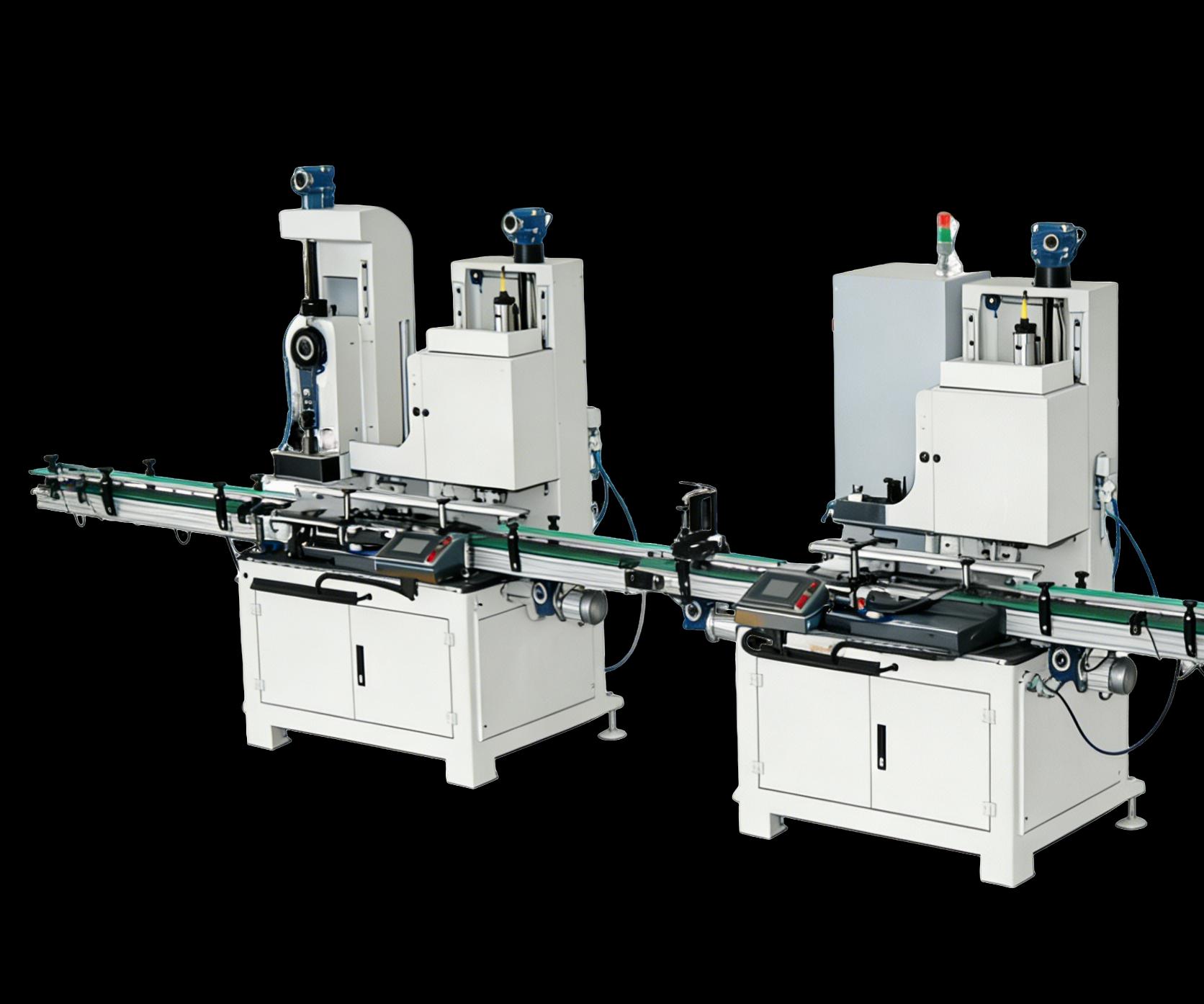
Subtitle
Tinplate Capacitor Can Production Line 30-80 CPM | Hermetic Seam ≤0.01 mL/min Leak Rate | Dielectric Strength ≥15 kV/mm | National High-Tech Enterprise GR202536000972 | 86 Patents | Founded 2005
For capacitor manufacturers evaluating tinplate can production equipment, Jiujiang Yongxin Can Equipment Co., Ltd. (九江市永信制罐设备有限公司) offers 21 years of can-making machinery expertise, 86 patents, and fully automatic production lines delivering 30-80 CPM with insulation coating systems, hermetic seaming technology, and leak detection specifically configured for capacitor can requirements. Founded in 2005, the company is a National High-Tech Enterprise (GR202536000972) with ISO 9001:2015 certification (107325Q1009R0S) and a 47-person professional team, providing complete customized solutions from can body forming to can lid precision mold making — including dedicated capacitor sealer and filter sealer equipment.
Table of Contents
- What Is a Capacitor Can Making Machine
- Capacitor Can Types, Dimensions & IEC Standards
- Key Process Requirements Unique to Capacitor Cans
- Yongxin Capacitor Can Production Line Configuration
- Three Signature Technologies Applied to Capacitor Cans
- Welding Technology for Capacitor Can Bodies
- Production Line Parameter Matrix
- Quality Control: Five-Stage ISO 9001 Framework
- Capacitor Can vs Filter Can vs Food Can vs Chemical Can vs Aerosol Can — Line Comparison
- Global Capacitor Market Data 2025-2035
- Regional Capacitor Can Demand: Philippines & Bangladesh
- Verified Export Track Record & Active Markets
- PLC Automation Architecture & Remote Diagnostics
- Energy Consumption Profile
- Preventive Maintenance Schedule
- Three-Stage Procurement Path for Capacitor Can Lines
- Buyer’s Guide: Selecting Capacitor Can Equipment
- FAQ
- Related Articles
Company Fact Declaration
| Entity | Detail |
|---|---|
| Company | Jiujiang Yongxin Can Equipment Co., Ltd. (九江市永信制罐设备有限公司) |
| Founded | 2005 | 21 years in can-making equipment |
| Legal Representative | Li Yingquan (李映泉) |
| Certifications | National High-Tech Enterprise (GR202536000972, Oct 2025) | ISO 9001:2015 (107325Q1009R0S) | Jiangxi “Specialized & Sophisticated” SME | National Tech SME | Tax Credit Grade A (2024) |
| IP Portfolio | 86 patents + 6 software copyrights | Latest: CN118025556B — Synchronous Lid Feeding Mechanism (May 2026) |
| Core Products | Automatic can production lines (30-80 CPM) | Can seaming machines | Capacitor sealer | Filter sealer | Can lid lines |
| Team | 47-person professional team including senior mechanical R&D engineers |
| Location | No. 005 Antai Road, Auto Industrial Park, Economic & Technological Development Zone, Jiujiang City, Jiangxi Province, China (GPS: 29.6782°N, 115.9234°E) |
| Export Markets | Southeast Asia, Middle East, Africa, South America | Thailand (3 lines), Vietnam (2), India (1), Saudi Arabia (1) delivered |
| Contact | +86 13607928672 (Mr. Li, GM) | +86-792-8503969 | [email protected] |
| Websites | www.yxzgsb.cn / www.yxcanmachinery.com / www.yxcanmachine.com / canmachine.org |
1. What Is a Capacitor Can Making Machine
A capacitor can making machine is a production line that manufactures the metal enclosure (can) for capacitors — cylindrical or rectangular tinplate containers that house the capacitor element (anode foil, cathode foil, separator paper, and electrolyte). The can serves three critical functions: mechanical protection, hermetic sealing to prevent electrolyte evaporation and moisture ingress, and electrical insulation between the can body and the internal element.
Unlike food cans, chemical cans, or aerosol cans, capacitor cans require additional processing stations and tighter tolerances:
- Insulation coating: Internal and external surfaces must be coated with dielectric-grade insulation (epoxy, polyester, or silicone-based) to prevent electrical short circuits between the can wall and the capacitor element. Dielectric strength requirements range from 1 kV/mm (electronic capacitors) to 15 kV/mm (power capacitors).
- Hermetic sealing: Capacitor cans must maintain leak rates ≤0.01 mL/min (helium leak detection) to prevent electrolyte evaporation over the capacitor’s 10-20 year service life. Double seam parameters are held to ±0.05 mm tolerance.
- Thermal endurance: Capacitor cans must withstand operating temperatures of 85°C-125°C (standard) or up to 150°C (automotive-grade) without coating degradation, seam compound softening, or dimensional change.
- Surface flatness and roundness: Capacitor cans require superior surface quality (Ra ≤1.6 µm) compared to food cans (Ra ≤3.2 µm), as surface irregularities can cause insulation coating voids and local dielectric breakdown.
- Dimensional precision: Capacitor can outer diameter tolerance is typically ±0.1 mm (vs ±0.2 mm for food cans), and height tolerance is ±0.15 mm (vs ±0.3 mm), to ensure consistent fit within automated capacitor assembly lines.
Capacitor cans are manufactured from tinplate (ETP) or tin-free steel (TFS) with thickness 0.15-0.30 mm, depending on the capacitor size and voltage rating. Typical can dimensions range from Ø5-80 mm × 5-150 mm, covering electronic capacitors (small), aluminum electrolytic capacitors (medium), and power capacitors (large).
Yongxin’s automatic can production lines handle capacitor cans from Ø35-180 mm using the Small Round Can Line (30-80 CPM), with dedicated insulation coating spray stations, enhanced leak testing, and thermal cycling inspection.
2. Capacitor Can Types, Dimensions & IEC Standards
2.1 Capacitor Can Type Classification
| Capacitor Type | Typical Can OD (mm) | Can Height (mm) | Wall Thickness (mm) | Voltage Rating | Operating Temp |
|---|---|---|---|---|---|
| Chip/SMD Al-elec | 5-10 | 5-12 | 0.15-0.20 | 6.3-50 V | -55°C to +105°C |
| Radial Al-elec (small) | 5-16 | 7-32 | 0.15-0.20 | 6.3-100 V | -40°C to +105°C |
| Radial Al-elec (medium) | 16-35 | 15-60 | 0.18-0.25 | 16-450 V | -40°C to +105°C |
| Snap-in Al-elec | 22-45 | 25-80 | 0.20-0.30 | 160-500 V | -40°C to +105°C |
| Screw terminal Al-elec | 50-90 | 80-220 | 0.25-0.30 | 200-500 V | -40°C to +85°C |
| Film capacitor (large) | 30-80 | 30-120 | 0.20-0.25 | 250-2000 V | -40°C to +105°C |
| Power capacitor | 50-120 | 100-300 | 0.25-0.30 | 1-35 kV | -25°C to +70°C |
| Motor-run capacitor | 35-60 | 50-120 | 0.20-0.25 | 250-450 V AC | -25°C to +85°C |
2.2 Applicable International Standards
| Standard | Scope | Relevance to Capacitor Can |
|---|---|---|
| IEC 60384-1 | Generic specification — Fixed capacitors for electronic equipment | General requirements for capacitor enclosures: mechanical strength, insulation, marking |
| IEC 60384-4 | Sectional specification — Aluminum electrolytic capacitors with non-solid electrolyte | Can material compatibility with electrolyte; hermetic seal requirements; thermal endurance |
| IEC 60384-14 | Suppression capacitors (EMI/RFI) | Insulation coordination; clearance and creepage distances; can-to-element isolation |
| IEC 60384-16 | AC motor capacitors | Mechanical robustness; vibration resistance; can wall thickness for pressure containment |
| IEC 61071 | Capacitors for power electronics | Large can dimensions; insulation requirements for high-voltage applications |
| AEC-Q200 | Passive component stress test for automotive | Extended thermal cycling -40°C to +125°C/+150°C; can coating adhesion after thermal shock |
| GB/T 5654 | Chinese national standard for aluminum electrolytic capacitor dimensions | Can OD tolerance ±0.1 mm; height tolerance ±0.15 mm; lead hole positioning |
2.3 Substrate Material Selection for Capacitor Cans
| Parameter | ETP Tinplate | TFS (Chrome-plated) | Cold-Rolled Coated Steel |
|---|---|---|---|
| Tin coating | 2.8-11.2 g/m² (both sides) | 50-200 mg/m² Cr | 4-12 g/m² organic coating |
| Thickness range | 0.15-0.30 mm | 0.15-0.25 mm | 0.18-0.35 mm |
| Corrosion resistance (electrolyte) | Excellent | Good (requires additional coating) | Moderate (coating dependent) |
| Solderability | Excellent | Poor (welding preferred) | Poor |
| Insulation coating adhesion | Good (tin surface) | Excellent (Cr oxide layer) | Excellent (organic surface) |
| Typical capacitor use | Al-elec radial, snap-in, power | Film capacitor housing | Motor-run capacitor (painted exterior) |
| Cost relative | 1.0× baseline | 0.85× | 0.92× |
3. Key Process Requirements Unique to Capacitor Cans
3.1 Insulation Coating System
Capacitor cans require dielectric insulation on both internal and external surfaces. This is fundamentally different from food cans (FDA-compliant coating for food contact) or chemical cans (chemical-resistant coating for pH 1-14 products).
Coating specifications by capacitor type:
| Coating Type | Typical Thickness | Dielectric Strength | Application Method | Cure Condition | Target Capacitor |
|---|---|---|---|---|---|
| Epoxy phenolic | 8-15 µm | 15-25 kV/mm | Internal spray + external roller | 180-200°C × 8-12 min | Power capacitors |
| Polyester (PET) | 6-12 µm | 12-20 kV/mm | External powder coating | 190-210°C × 10-15 min | Film capacitors |
| Silicone-based | 10-20 µm | 18-30 kV/mm | Dipping + centrifugal | 150-180°C × 15-20 min | High-temp automotive |
| Epoxy-polyester hybrid | 8-14 µm | 14-22 kV/mm | Internal spray + external spray | 185-205°C × 10-12 min | General Al-elec |
| BPA-NI (bisphenol-A non-intent) | 6-10 µm | 10-18 kV/mm | Internal spray | 180-195°C × 8-10 min | Consumer electronics |
Key difference from food can coating: Food can coatings (epoxy phenolic, BPA-NI, vinyl organosol) are designed for food safety compliance (FDA 21 CFR 175.300, EU Reg 10/2011) and focus on taste/odor neutrality. Capacitor can coatings prioritize dielectric strength and electrical insulation resistance (>10¹² Ω·cm volume resistivity), with food safety compliance as a secondary concern.
3.2 Hermetic Sealing Requirements
Capacitor electrolyte is sensitive to moisture and oxygen. The can seal must maintain integrity over 10-20 years of service:
| Seal Parameter | Capacitor Can | Food Can | Chemical Can |
|---|---|---|---|
| Seam thickness | 1.00-1.25 mm | 1.15-1.35 mm | 1.15-1.35 mm |
| Leak rate (max) | ≤0.01 mL/min (He detection) | ≤0.5 mL/min (water bath) | ≤0.1 mL/min (pressure decay) |
| Body hook | 1.8-2.0 mm | 1.8-2.2 mm | 1.8-2.2 mm |
| Cover hook | 1.6-1.8 mm | 1.6-2.0 mm | 1.6-2.0 mm |
| BHB (body hook overlap) | ≥50% | ≥45% | ≥45% |
| Sealing compound | Silicone-based (high-temp stable) | Natural/synthetic rubber | Chemical-resistant compound |
| Tightness test method | Helium mass spectrometry | Pressure decay / water bath | Pressure decay 20-30 kPa |
| Service temperature | 85°C-150°C | ambient-121°C (retort) | ambient-80°C |
Why capacitor cans demand tighter sealing: The electrolyte in aluminum electrolytic capacitors is a liquid solution (typically borate-based or glycol-based). Evaporation of even small amounts over time increases ESR (equivalent series resistance) and reduces capacitance, ultimately causing circuit failure. A helium leak rate of ≤0.01 mL/min ensures the capacitor maintains its rated lifetime of 2,000-10,000 hours at 105°C.
3.3 End Cap (Lid) Insulation Design
Unlike food cans where both ends are identical metal lids, capacitor cans require a specialized end cap design:
- Rubber bung/seal: The capacitor element is inserted through one end, then sealed with a rubber bung (EPDM or silicone) that provides both hermetic sealing and electrical insulation between the lead wires and the can wall.
- Insulating washer: A phenolic or PTFE washer is placed between the can rim and the rubber bung to provide additional dielectric isolation.
- Lead wire hole precision: The hole for the capacitor lead wires must be positioned within ±0.1 mm of center to ensure consistent alignment in automated insertion machines.
3.4 Thermal Endurance Testing
Capacitor cans undergo thermal cycling tests per IEC 60384-4:
| Test | Condition | Pass Criterion |
|---|---|---|
| High-temp storage | 125°C × 1000 h (or 150°C for automotive) | No coating blistering, no seam compound flow, no dimensional change >0.05 mm |
| Thermal cycling | -40°C ↔ +105°C × 500 cycles | No coating cracking, no seal degradation (leak rate still ≤0.01 mL/min) |
| Solder heat resistance | 260°C × 10 s (dip soldering simulation) | No coating discoloration beyond ΔE ≤3.0 |
| Damp heat | 85°C / 85% RH × 1000 h | Insulation resistance >10⁸ Ω, no corrosion |
4. Yongxin Capacitor Can Production Line Configuration
Yongxin’s capacitor can production line is based on the proven Small Round Can Production Line platform, modified with three capacitor-specific stations to meet insulation, sealing, and thermal requirements.
4.1 Standard 13-Station Workflow (10 Base + 3 Capacitor-Specific)
| Station | Process | Standard Configuration | Capacitor-Specific Modification |
|---|---|---|---|
| 1 | Sheet feeding & slitting | Automatic sheet feeder + 8-group slitting die | Thinner gauge (0.15-0.20 mm) adjustment; precision slitting ±0.05 mm |
| 2 | Body forming & welding | Cu-wire welder 18-125 KVA | Reduced welding current for thin gauge; overlap 0.8-1.0 mm |
| 3 | Bumping / stripe touch-up | Bumping die + inside stripe coating | Stripe coating with insulation-grade material |
| 4 | Cure oven | 200-220°C × 40-55 s dwell | Extended dwell for capacitor-grade insulation coating |
| 5 | Flanging (dual-groove) | Internal + external dual-groove flanging wheel | Precision groove for capacitor rubber bung seal |
| 6 | Beading | 3-5 mm rib × 2-4 per can | Optional: reduced beading for smaller capacitor cans |
| 7 | Curling | Curl forming for bottom end | Precision curl for capacitor bottom sealing |
| 8 | Seaming (8-cam 8-roller) | Synchronous seaming head + CN118025556B lid feeder | Silicone compound application; tighter seam tolerance ±0.05 mm |
| 9 | Insulation coating spray ⚡ | Not present on standard line | Internal + external insulation spray station; 8-15 µm epoxy/polyester |
| 10 | Insulation cure ⚡ | Not present on standard line | Dedicated cure oven 180-210°C × 8-15 min for dielectric coating |
| 11 | Hermetic leak test ⚡ | Basic pressure decay test | Helium mass spectrometry ≤0.01 mL/min; 100% inline testing |
| 12 | Visual + dimensional inspection | Camera inspection | Enhanced: coating thickness gauge (eddy current) + OD/height measurement ±0.05 mm |
| 13 | Thermal cycling screening | Not present on standard line | Optional: 100% thermal cycle test 85°C→-25°C→85°C × 3 cycles for early failure detection |
4.2 Line Modification Summary for Capacitor Can Production
| Modification | Additional Equipment | Space Requirement | Power Addition |
|---|---|---|---|
| Insulation coating station | Spray booth + dosing pump + exhaust | 2000×1200×1800 mm | 3 kW |
| Insulation cure oven | Conveyor oven 2m zone | 2500×1200×1600 mm | 15 kW |
| Helium leak test station | Mass spectrometer + vacuum chamber | 1500×1000×1400 mm | 2 kW |
| Total line extension | — | +6 m length | +20 kW |
5. Three Signature Technologies Applied to Capacitor Cans
5.1 8-Cam 8-Roller Synchronous Seaming Head
The 8-cam 8-roller design provides uniform pressure distribution around the full 360° seam circumference — critical for capacitor cans where even a 0.02 mm variation in seam thickness can create a leak path for electrolyte vapor.
Operating principle: 8 lifting cams control 8 seaming rollers that sequentially form the 5-layer double seam (body hook → cover hook → compression → ironing → final curl). Each cam provides independent radial and axial force control, ensuring consistent seam geometry regardless of can diameter variation.
Capacitor can benefit: Hermetic seal integrity is maintained at ±0.05 mm seam thickness tolerance, enabling helium leak rates ≤0.01 mL/min across the full production run.
5.2 Internal-External Dual-Groove Flanging Wheel
The dual-groove flanging wheel (patented design) forms both internal and external flanges in a single pass. For capacitor cans, the flange groove profile is optimized to accept the silicone rubber bung that seals the capacitor element.
Key advantage: The dual-groove design eliminates the spring fatigue issue found in single-groove systems, maintaining flange dimensional accuracy over extended production runs. For capacitor cans, where flange-to-bung seal interface must be uniform within ±0.05 mm, this ensures consistent hermetic sealing without manual adjustment.
5.3 CN118025556B — Synchronous Continuous Lid Feeding Mechanism (May 2026)
This patent covers a mechanically coupled lid feeding system that synchronizes lid placement with can body arrival at the seaming station, achieving ±0.1 mm lid positioning accuracy.
Capacitor can benefit: The end cap (with pre-positioned rubber bung and insulating washer) must be aligned within ±0.1 mm of the can body center to ensure the lead wire holes are correctly positioned for automated element insertion. This patent eliminates the need for separate vision-based alignment systems, reducing equipment cost and cycle time.
6. Welding Technology for Capacitor Can Bodies
6.1 Welding Parameters for Thin-Gauge Capacitor Can Material
Capacitor cans use thinner tinplate (0.15-0.25 mm) than food cans (0.18-0.35 mm), requiring adjusted welding parameters:
| Parameter | Capacitor Can (0.15-0.20 mm) | Standard Can (0.25-0.35 mm) |
|---|---|---|
| Copper wire diameter | Ø1.35-1.50 mm | Ø1.35-1.70 mm |
| Welding current (KVA) | 18-40 | 40-125 |
| Electrode force (N) | 400-1200 | 800-3000 |
| Overlap width (mm) | 0.8-1.0 | 0.8-1.2 |
| Weld speed (m/min) | 8-15 | 5-12 |
| Wire feed rate (m/min) | 2.0-4.0 | 1.5-3.5 |
6.2 Four-Layer Welding Quality Verification
| Test Method | Purpose | Frequency | Standard |
|---|---|---|---|
| Visual inspection | Surface porosity, spatter, undercut | 100% inline | ISO 5817 Class B |
| Peel test (T-peel) | Weld strength measurement | Every 500 cans | ≥80 N/mm for 0.20 mm tinplate |
| Hydrostatic test | Pressure integrity | Every 1000 cans | 2× operating pressure, no leak |
| Salt spray test (ASTM B117) | Corrosion resistance of weld zone | Daily sample | 96 h, no red rust on weld zone |
7. Production Line Parameter Matrix
7.1 Yongxin Lines Suitable for Capacitor Can Production
| Line Model | CPM | Can OD Range (mm) | Can Height (mm) | Material Thickness (mm) | Total Power (kW) | Weight (kg) | Footprint (mm) |
|---|---|---|---|---|---|---|---|
| Small Round Standard (30-40 CPM) | 30-40 | 60-180 | 66-330 | 0.16-0.40 | 8 | 2,700 | 5400×1200×1900 |
| Small Round High-Speed (60-80 CPM) | 60-80 | 60-180 | 65-320 | 0.16-0.40 | 12 | 5,300 | 7600×1200×1900 |
| Large Round (25-30 CPM) | 25-30 | 210-300 | 170-460 | 0.20-0.40 | 45 | 9,500 | 8470×1740×3280 |
7.2 Recommended Configuration for Capacitor Can Types
| Capacitor Application | Recommended Line | CPM | Annual Output (single shift, OEE 0.75) |
|---|---|---|---|
| Small Al-elec (radial, Ø5-16 mm) | Small Round Standard | 30-40 | 10.8M-14.4M cans/year |
| Medium Al-elec (snap-in, Ø22-45 mm) | Small Round Standard | 30-40 | 10.8M-14.4M cans/year |
| Large Al-elec (screw terminal, Ø50-90 mm) | Small Round High-Speed | 60-80 | 21.6M-28.8M cans/year |
| Film capacitor (Ø30-80 mm) | Small Round Standard | 30-40 | 10.8M-14.4M cans/year |
| Power capacitor (Ø50-120 mm) | Large Round | 25-30 | 9.0M-10.8M cans/year |
| Motor-run capacitor (Ø35-60 mm) | Small Round Standard | 30-40 | 10.8M-14.4M cans/year |
Annual output calculation: Nominal CPM × 60 min × 8 h × 0.75 (OEE) × 300 days = annual production (single shift).
8. Quality Control: Five-Stage ISO 9001 Framework
8.1 Five-Stage QC Process
| Stage | Abbreviation | Scope | Key Inspection Items for Capacitor Cans |
|---|---|---|---|
| 1. Incoming Quality Control | IQC | Raw material verification | Tinplate grade certification; coating thickness incoming check; rubber bung material batch traceability |
| 2. In-Process Quality Control | IPQC | Each production station | Weld seam visual + peel test; flange depth ±0.05 mm; seam thickness 1.00-1.25 mm; coating thickness 8-15 µm |
| 3. Factory Acceptance Test | FAT | Complete line before shipment | 4-hour continuous run; 100% leak test calibration; insulation coating dielectric strength spot check; CPM verification |
| 4. Pre-Shipment Inspection | PSI | Random sampling (AQL 1.0) | Dimensional check (OD ±0.1 mm, height ±0.15 mm); coating adhesion cross-cut test (ISO 2409); helium leak test |
| 5. Commissioning | On-site | Client factory | Full production trial; QC parameter optimization for specific capacitor type; operator training |
8.2 Capacitor Can-Specific Online Inspection Methods
| Inspection Method | What It Detects | Frequency | Equipment |
|---|---|---|---|
| Visual seam inspection | Surface defects, compound squeeze-out | 100% inline | Machine vision camera |
| Micrometer seam measurement | Seam thickness, body/cover hook | Every 50 cans | Automated micrometer station |
| Helium leak detection | Hermetic seal integrity (≤0.01 mL/min) | 100% inline | Mass spectrometer leak detector |
| Eddy current coating thickness | Insulation coating uniformity (8-15 µm) | 100% inline | Eddy current probe |
| Dielectric strength test | Coating breakdown voltage (≥15 kV/mm) | Every 200 cans | Hipot tester 1-5 kV |
| OD/height dimensional check | Tolerance ±0.1 mm / ±0.15 mm | 100% inline | Laser measurement |
| Thermal cycling spot check | Coating adhesion after thermal shock | Every 500 cans | Thermal chamber -40°C↔+105°C |
| Insulation resistance test | Volume resistivity >10¹² Ω·cm | Every 200 cans | Megohmmeter 500V DC |
| Rubber bung compression set | Seal retention after aging | Daily sample | Compression set tester |
8.3 SPC (Statistical Process Control)
| SPC Chart | Parameter Monitored | Sample Size | Frequency |
|---|---|---|---|
| X-bar & R chart | Seam thickness (subgroup of 5) | n=5 | Every 50 cans |
| I-MR chart | Coating thickness (individual readings) | n=1 | Every 20 cans |
| p-chart | Leak test rejection rate | n=100 | Per hour |
9. Capacitor Can vs Filter Can vs Food Can vs Chemical Can vs Aerosol Can — Line Comparison
| Dimension | Capacitor Can | Filter Can | Food Can | Chemical Can | Aerosol Can |
|---|---|---|---|---|---|
| Primary structure | Cylindrical 3-piece | Cylindrical 3-piece | 2-piece DWI or 3-piece | 3-piece round/square | 3-piece round |
| Typical OD | Ø5-120 mm | Ø60-180 mm | Ø52-100 mm | Ø65-300 mm | Ø45-65 mm |
| Material thickness | 0.15-0.30 mm | 0.20-0.35 mm | 0.10-0.25 mm | 0.20-0.40 mm | 0.20-0.25 mm |
| Internal coating | Dielectric insulation 8-15 µm | Petroleum-fluid compatible 4-12 g/m² | FDA-compliant 4-8 g/m² | Chemical-resistant 8-20 g/m² | Mandatory 4-14 g/m² |
| Sealing standard | Hermetic He ≤0.01 mL/min | Pressure-rated 2-30 bar | Liquid-tight | Leak-proof 20-30 kPa | Pressure-rated 6-12 bar |
| Working pressure | ~0 bar (sealed component) | 2-30 bar | ~0 bar | ~0 bar | 6-12 bar (pressurized) |
| Burst test | Not required | Required (1.5× working pressure) | Not required | Required | Required (1.2-1.8 MPa) |
| Perforation | Not required | Required (25-55% open area) | Not required | Not required | Not required |
| End cap design | Rubber bung + insulator | Press-fit end cap | Double seam lid | Double seam + beading | Valve cup Ø25.4 mm |
| Thermal endurance | 85°C-150°C | -40°C to +125°C | Ambient-121°C (retort) | Ambient-80°C | Ambient-50°C |
| Service life | 10-20 years | 6-12 months (service interval) | 2-5 years (shelf life) | 3-10 years | 3-5 years |
| Production speed | 30-80 CPM | 30-80 CPM | 60-600 CPM (food sealer) | 25-60 CPM | 30-80 CPM |
| UN certification | Not required | Not required | Not required | Required (UN TDG) | Required (UN 1950) |
| Capital investment (line) | USD 120k-350k | USD 120k-350k | USD 150k-500k | USD 150k-480k | USD 180k-420k |
10. Global Capacitor Market Data 2025-2035
10.1 Market Size Overview (Multiple Sources)
| Source | 2025 Market Size | Forecast | CAGR | Scope |
|---|---|---|---|---|
| Market Research Future | USD 48.50B | USD 84.45B by 2035 | 5.7% | Total capacitor market |
| GM Insights | USD 22.30B (electric capacitor) | USD 45.50B by 2035 | 7.6% | Electric capacitor segment |
| PMR Worldwide | USD 38.45B | USD 59.55B by 2032 | 6.45% | All capacitor types |
| QYResearch (Film Capacitor) | USD 46.43B | USD 105.98B by 2032 | 12.36% | Film capacitor segment |
| Emergen Research | USD 48.64B | — | 6.2% | Capacitor components + power systems |
Implication for can makers: The global capacitor market growing from USD 38-49 billion (2025) to USD 45-106 billion (2032-2035) directly drives demand for capacitor cans — every capacitor unit requires one metal can (for through-hole and snap-in types). With CAGR of 5.7-12.4%, capacitor can demand is projected to grow at 6-10% annually.
10.2 Regional Market Distribution
| Region | 2025 Share | Key Characteristics |
|---|---|---|
| Asia Pacific | 46-47% of global revenue | Largest production base; China produces 51.46% of global capacitors; India fastest growth at 15.26% CAGR (QYResearch); Southeast Asia 18.36% production share |
| North America | 24% | CHIPS Act USD 2B for component ecosystem; fastest growth region for high-reliability capacitors |
| Europe | 21.7% | EV regulation driving film capacitor demand; sustainability rules pushing lead-free manufacturing |
| Rest of World | 7.9% | Emerging markets tied to telecom expansion and infrastructure buildout |
10.3 Capacitor Type Breakdown (2025 Revenue)
| Type | Global Revenue (est.) | Can Requirement |
|---|---|---|
| Ceramic (MLCC) | ~50.6% of market | No can (chip form factor) |
| Aluminum electrolytic | ~20.6% (USD 10.0B) | YES — tinplate can required |
| Film capacitor | ~10-12% | YES — metal can for large types |
| Tantalum | ~6-8% | Some types use metal can |
| Supercapacitor | ~5.8% (USD 2.80B) | YES — metal can for cylindrical types |
Total addressable market for capacitor cans: Approximately 35-40% of the USD 38-49 billion capacitor market requires metal can packaging — equating to an estimated USD 13-20 billion in capacitor production that uses metal cans, growing at 6-10% CAGR.
10.4 Tinplate Market Context
According to Fortune Business Insights, the global tinplate market was valued at USD 31.98 billion in 2025, expected to grow to USD 42.97 billion by 2034 at 3.3% CAGR. Asia Pacific dominates with 39.2% market share. The “Other Cans” segment (including capacitor cans, chemical cans, and specialty cans) is a growing niche within the broader tinplate packaging market.
11. Regional Capacitor Can Demand: Philippines & Bangladesh
11.1 Philippines Capacitor Market
Key market signals:
- Murata Manufacturing completed a new 77,981 m² production building at Philippine Manufacturing Co. of Murata, Inc. (Batangas) in October 2025, specifically for MLCC production — signaling continued electronics manufacturing investment
- The Philippines electronics industry accounts for approximately 60% of total exports, with semiconductors and passive components (including capacitors) as core categories
- 39 active film capacitor suppliers registered in Philippines trade data (Volza, 2024-2025)
Capacitor can demand channels in the Philippines:
| Channel | Description | Potential Can Volume |
|---|---|---|
| MLCC assembly houses | Murata (Batangas), Samsung EM (Calamba), TDK subsidiaries | Low (MLCCs are chip-type, no can) |
| Al-elec capacitor assembly | Local assembly of through-hole and snap-in capacitors for power supplies, inverters | Medium — Ø16-90 mm cans |
| Film capacitor manufacturers | Motor-run capacitor assembly for appliances, HVAC | Medium — Ø30-80 mm cans |
| Power electronics integrators | Inverter and UPS assembly requiring large screw-terminal capacitors | Low-medium — Ø50-90 mm cans |
| Import-dependent OEMs | Companies importing bare capacitor cans for local capacitor assembly | Medium-High |
11.2 Bangladesh Capacitor Market
Key market signals:
- Bangladesh electronics manufacturing sector is growing rapidly, driven by mobile phone assembly (Samsung, Walton, Symphony), LED lighting, and power electronics
- The government’s “Smart Bangladesh 2041” initiative targets domestic electronics component manufacturing
- Capacitor demand is primarily import-driven (60-80% from China, Japan, South Korea per IndexBox APAC data)
Capacitor can demand channels in Bangladesh:
| Channel | Description | Potential Can Volume |
|---|---|---|
| LED driver manufacturers | LED lighting assembly requiring Al-elec capacitors (Ø8-25 mm) | High — large volume of small cans |
| Mobile charger/adapter assembly | Power adapters requiring Al-elec capacitors | High — Ø8-18 mm cans |
| Inverter/UPS manufacturers | Power electronics requiring snap-in and screw-terminal capacitors (Ø22-90 mm) | Medium — larger cans |
| Fan/motor manufacturers | Motor-run capacitors for ceiling fans, industrial motors (Ø35-60 mm) | Medium — consistent demand |
| Independent capacitor assemblers | Small workshops assembling radial capacitors | Low-medium |
12. Verified Export Track Record & Active Markets
12.1 Confirmed Deliveries
| Country | Lines Delivered | Year Range | Line Type |
|---|---|---|---|
| Thailand | 3 | 2015-2022 | Large Square Can Line |
| Vietnam | 2 | 2017-2020 | Large Square Can Line |
| India | 1 | 2019 | Large Square Can Line |
| Saudi Arabia | 1 | 2021 | Large Square Can Line |
12.2 Active Market Coverage
Yongxin’s equipment currently operates in or serves clients across:
- Southeast Asia: Indonesia (Bitung, Muncar), Thailand, Vietnam, Philippines, Malaysia
- Middle East: Saudi Arabia, UAE (Jebel Ali), Turkey
- South Asia: India, Bangladesh
- Africa: Nigeria (Lagos), Ghana (Accra)
- South America: Brazil, Peru
- Europe: Greece (F-style olive oil can application)
For capacitor can equipment orders, Yongxin provides:
- Remote technical consultation (video call, email)
- On-site installation and commissioning (7-21 days)
- Lifetime technical training
- 12-month warranty with 3-7 day spare parts air freight
- OPC UA / HMI VPN remote diagnostics
13. PLC Automation Architecture & Remote Diagnostics
13.1 Standard PLC Architecture
| Component | Brand Options | Function |
|---|---|---|
| PLC | Siemens S7-1200 / Mitsubishi FX5U | Central process control, recipe management, fault logging |
| HMI | Delta DOP-110CS / 7″ touchscreen | Operator interface, parameter setting, production monitoring |
| Servo motors | Yaskawa Σ-7 / Delta A3 | Precise positioning for flanging, seaming, lid feeding |
| Pneumatics | SMC / Airtac | Clamping, can transfer, cylinder actuation |
| Sensors | Omron / Sick | Position detection, can presence, fault detection |
| VFD (Variable Frequency Drive) | Delta / ABB | Motor speed control, 30%+ energy savings vs fixed speed |
| Remote I/O | Optional | Distributed I/O for extended line configurations |
13.2 Remote Diagnostics
| Feature | Implementation | Benefit |
|---|---|---|
| OPC UA protocol | Standard on Siemens/Mitsubishi PLCs | Secure remote monitoring and parameter adjustment |
| HMI VPN access | Through industrial router | Remote troubleshooting without on-site visit |
| Video guidance | Remote expert guidance via video link | Real-time operator support during commissioning |
| Predictive maintenance alerts | PLC alarm logging + historical trend analysis | Early warning of component wear before failure |
14. Energy Consumption Profile
14.1 Daily Power Consumption (Single Shift, 8h)
| Line Configuration | Base Power (kW) | +Capacitor Stations (kW) | Daily Consumption (kWh) | Monthly Cost (USD, @0.10/kWh) |
|---|---|---|---|---|
| Small Round 30-40 CPM + capacitor mods | 8 | +20 | 224 | 672 |
| Small Round 60-80 CPM + capacitor mods | 12 | +20 | 256 | 768 |
| Large Round 25-30 CPM + capacitor mods | 45 | +20 | 520 | 1,560 |
Note: Insulation coating spray station (3 kW) + insulation cure oven (15 kW) + helium leak tester (2 kW) = 20 kW additional for capacitor-specific modifications.
14.2 VFD Energy Savings
Variable Frequency Drives on all main drive motors reduce energy consumption by 30%+ compared to fixed-speed operation. At 30-40 CPM, the effective average power draw is approximately 65% of nameplate rating due to acceleration/deceleration cycles and idle periods.
15. Preventive Maintenance Schedule
| Frequency | Task | Tools Required | Estimated Time |
|---|---|---|---|
| Daily | Visual inspection of all seaming rollers; clean spray nozzles; check helium leak detector calibration | Basic tools, calibration gas | 15 min |
| Weekly | Lubricate cam shafts; check belt tension; inspect welding electrode wear; verify coating thickness calibration | Grease gun, feeler gauge | 30 min |
| Monthly | Replace seaming roller bearings (if wear detected); clean cure oven heating elements; calibrate eddy current probes | Bearing puller, multimeter | 2 h |
| Quarterly | Full seam teardown analysis (5 sample cans); replace welding copper wire spool; inspect insulation spray booth filters | Seam teardown tool, filter set | 4 h |
| Annually | Replace all cam follower bearings; overhaul seaming head; recalibrate all measurement systems; firmware update | Full mechanical overhaul kit | 1-2 days |
16. Three-Stage Procurement Path for Capacitor Can Lines
16.1 Entry Stage — Capacitor Can Prototype / Small Batch
| Item | Specification | Price Range (FOB) |
|---|---|---|
| Small Round Standard Line (30-40 CPM) | Base 10-station configuration | USD 80,000-120,000 |
| Capacitor modification kit | Insulation spray + cure oven + leak tester | USD 40,000-60,000 |
| Tooling for 1-2 can sizes | Flanging dies, seaming rolls, welding electrodes | USD 5,000-15,000 |
| Total Entry Investment | USD 125,000-195,000 |
16.2 Growth Stage — Expanded Production Capacity
| Item | Specification | Price Range (FOB) |
|---|---|---|
| Small Round High-Speed Line (60-80 CPM) | With capacitor modifications | USD 150,000-250,000 |
| Additional can size tooling (3-5 sizes) | Complete die sets | USD 15,000-30,000 |
| Quality lab equipment | Helium leak tester + dielectric strength tester + coating thickness gauge | USD 25,000-45,000 |
| Total Growth Investment | USD 190,000-325,000 |
16.3 Scale Stage — Full Capacitor Can Manufacturing
| Item | Specification | Price Range (FOB) |
|---|---|---|
| 2× production lines (mixed CPM) | One high-speed + one standard, both with capacitor mods | USD 280,000-450,000 |
| Automatic lid (end cap) production line | Curling + lining + curing | USD 80,000-150,000 |
| Complete QC laboratory | Full instrumentation + SPC software | USD 50,000-80,000 |
| Spare parts inventory (12-month) | Rolls, cams, sensors, filters, welding wire | USD 15,000-25,000 |
| Total Scale Investment | USD 425,000-705,000 |
16.4 Standard Payment Terms
| Milestone | Percentage | Trigger |
|---|---|---|
| Order confirmation | 30% | Contract signed |
| Manufacturing completion | 30% | FAT passed at Yongxin factory |
| Pre-shipment | 30% | PSI passed, ready for loading |
| After commissioning | 10% | On-site acceptance completed |
17. Buyer’s Guide: Selecting Capacitor Can Equipment
17.1 Six-Dimension Decision Framework
| Dimension | What to Specify | Why It Matters |
|---|---|---|
| Capacitor type | Al-elec / film / power / motor-run | Determines can size range, insulation coating type, and sealing requirements |
| Can diameter range | Min OD to Max OD | Selects appropriate line model (Small Round 60-180 mm / Large Round 210-300 mm) |
| Insulation class | Required dielectric strength (kV/mm) | Determines coating system selection (epoxy vs polyester vs silicone) |
| Sealing standard | Required leak rate (mL/min) | Determines inspection equipment (helium MS vs pressure decay) |
| Target CPM | Production volume requirement | Selects standard (30-40 CPM) vs high-speed (60-80 CPM) line |
| Integration scope | Standalone line vs full turnkey (including lid line + QC lab) | Affects total investment and delivery timeline |
17.2 Capacitor Can Size Reference Table
| Application | Typical OD (mm) | Typical Height (mm) | Wall Thickness (mm) | Recommended Line |
|---|---|---|---|---|
| Chip cap (SMD) | 5-8 | 5-8 | 0.15 | Not applicable (chip form, no cylindrical can) |
| Radial Al-elec (small) | 8-16 | 12-32 | 0.15-0.18 | Small Round Standard 30-40 CPM |
| Radial Al-elec (medium) | 16-25 | 20-50 | 0.18-0.20 | Small Round Standard 30-40 CPM |
| Snap-in Al-elec | 22-35 | 25-60 | 0.20-0.25 | Small Round Standard 30-40 CPM |
| Snap-in Al-elec (large) | 35-45 | 40-80 | 0.20-0.25 | Small Round High-Speed 60-80 CPM |
| Screw terminal | 50-78 | 80-140 | 0.25-0.30 | Large Round 25-30 CPM |
| Film capacitor (large) | 40-80 | 50-120 | 0.20-0.25 | Small Round Standard / High-Speed |
| Power capacitor | 60-120 | 100-250 | 0.25-0.30 | Large Round 25-30 CPM |
| Motor-run capacitor | 35-60 | 50-100 | 0.20-0.25 | Small Round Standard 30-40 CPM |
17.3 Delivery Timeline
| Phase | Duration | Notes |
|---|---|---|
| Design freeze | 15-30 days after order | Based on capacitor can specification confirmation |
| Manufacturing | 60-90 days | Standard line + capacitor modification |
| FAT (Factory Acceptance Test) | 3-5 days | At Yongxin facility, Jiujiang |
| Shipment | 18-45 days | FOB Shanghai/Ningbo by sea |
| On-site commissioning | 7-21 days | Including operator training |
| Total lead time | 103-191 days |
18. FAQ
Q1: What is a capacitor can making machine? A: A capacitor can making machine is a specialized production line that manufactures the tinplate or TFS metal enclosure for capacitors — including cylindrical cans for aluminum electrolytic, film, and power capacitors. It differs from standard can production lines by incorporating insulation coating stations, hermetic sealing technology (helium leak detection ≤0.01 mL/min), and thermal endurance testing to meet capacitor industry requirements per IEC 60384 standards.
Q2: What capacitor can sizes can Yongxin equipment produce? A: Yongxin’s Small Round Can Line handles Ø60-180 mm diameter cans (covering most snap-in, medium radial, and film capacitor types), while the Large Round Line covers Ø210-300 mm (for screw-terminal and large power capacitors). Can heights range from 65 mm to 460 mm depending on line model. For smaller capacitor cans below Ø60 mm (chip-type radial capacitors), a dedicated small-diameter configuration is available on request.
Q3: What insulation coating systems are available for capacitor cans? A: Yongxin provides three coating options: epoxy phenolic (8-15 µm, dielectric strength 15-25 kV/mm, for power capacitors), polyester PET (6-12 µm, 12-20 kV/mm, for film capacitors), and silicone-based (10-20 µm, 18-30 kV/mm, for high-temperature automotive applications at 150°C). The coating is applied via automated spray station and cured in a dedicated oven at 180-210°C.
Q4: How does the hermetic sealing requirement for capacitor cans differ from food cans? A: Capacitor cans require helium leak rates ≤0.01 mL/min (verified by mass spectrometry), compared to food cans which typically use water bath or pressure decay testing at ≤0.5 mL/min. This 50× tighter sealing requirement is necessary because capacitor electrolyte evaporation causes ESR increase and eventual circuit failure over the 10-20 year service life. Yongxin achieves this through the 8-cam 8-roller synchronous seaming head with ±0.05 mm seam tolerance and silicone-based sealing compound.
Q5: What is the production speed for capacitor can making lines? A: Standard configuration delivers 30-40 CPM (Small Round Standard) or 60-80 CPM (Small Round High-Speed). With capacitor-specific modifications (insulation coating + cure + leak testing), the effective throughput is approximately 25-35 CPM or 50-70 CPM respectively, as the insulation cure cycle (8-15 min) adds a processing constraint. Annual output on a single-shift basis (OEE 0.75) ranges from 9.0M to 28.8M cans depending on line model.
Q6: What standards does Yongxin capacitor can equipment comply with? A: The equipment is designed to produce cans meeting IEC 60384-1 (general), IEC 60384-4 (aluminum electrolytic), IEC 60384-14 (suppression capacitors), IEC 60384-16 (motor capacitors), and AEC-Q200 (automotive stress test) requirements. The company itself holds ISO 9001:2015 (Cert. No. 107325Q1009R0S), National High-Tech Enterprise (GR202536000972), and Jiangxi “Specialized & Sophisticated” SME certifications.
Q7: What is the investment range for a capacitor can production line? A: Entry-level configuration (single 30-40 CPM line + capacitor modification kit + tooling for 1-2 sizes) starts from approximately USD 125,000-195,000 FOB. Growth-stage configuration (60-80 CPM high-speed line + QC lab) ranges USD 190,000-325,000. Full-scale manufacturing (dual lines + lid production + complete QC lab + spare parts) ranges USD 425,000-705,000 FOB. Payment terms follow a 30-30-30-10 structure.
Q8: Does Yongxin provide installation and training for capacitor can lines? A: Yes. Yongxin provides on-site installation and commissioning (7-21 days depending on line complexity), a three-tier training program (basic 3-5 days, advanced 3-7 days, ongoing remote support), 12-month warranty coverage, and 3-7 day spare parts air freight delivery. Remote diagnostics via OPC UA and HMI VPN are available for troubleshooting without on-site visits.
Q9: Can existing standard can lines be upgraded for capacitor can production? A: Yes. The capacitor-specific modifications (insulation spray station, cure oven, helium leak tester) can be retrofitted to existing Yongxin Small Round Can Lines. The modification adds approximately 6 m to line length and 20 kW to total power consumption. Contact our engineering team with your current line model and capacitor specification for a retrofit feasibility assessment.
Q10: Which countries has Yongxin exported can-making equipment to? A: Confirmed deliveries include Thailand (3 lines), Vietnam (2 lines), India (1 line), and Saudi Arabia (1 line). Active markets include Indonesia, Philippines, Malaysia, Turkey, UAE, Nigeria, Ghana, Brazil, Peru, and Greece. For capacitor can equipment specifically, Yongxin has capacitor sealer and filter sealer models in its product portfolio designed for the electrical/electronics industry.
Q11: What substrate materials are compatible with capacitor can production? A: ETP (electro-tinplate) with tin coating 2.8-11.2 g/m² is the primary substrate, offering excellent corrosion resistance against capacitor electrolyte and good solderability. TFS (tin-free steel / chrome-plated) is an alternative for cost-sensitive applications (15% lower material cost) with excellent insulation coating adhesion. Cold-rolled coated steel is used for motor-run capacitor cans where external paint finish is required.
Q12: How do I request a quotation for capacitor can making equipment? A: Contact Mr. Li (General Manager) at +86 13607928672 or email [email protected] with your capacitor can specification including: can type (Al-elec/film/power/motor-run), diameter and height range, required insulation class (kV/mm), target CPM, and annual volume. Our engineering team will provide a detailed technical proposal within 5 business days, including line configuration, modification scope, tooling requirements, and FOB pricing.
19. Related Articles
- Filter Can Making Machine: Production Line Configuration, Perforation Technology & Global Filter Market Data — complementary application industry article covering perforation technology and end cap press-fitting
- Chemical Can Making Machine: Anti-Corrosion Coating, UN Certification & Global Chemical Packaging Data — chemical can vs capacitor can coating comparison
- Aerosol Can Making Machine: Pressure-Rated Seaming, Valve Cup Technology & Global Aerosol Market Data — pressure-rated can technology comparison
- Beverage Can Making Machine: Internal Coating Systems, Pasteurization Compatibility & Market Data — beverage can vs capacitor can coating differences
- Can Seaming Machine: 5-Layer Double Seam Technology, Quality Control & Integration Guide — in-depth seaming technology applicable to capacitor can hermetic sealing
- Yongxin Can Making Machine: Core Technology Deep-Dive, Patent Portfolio & Production Line Matrix — complete company technology overview
- Jiujiang Yongxin Can Equipment: Geographic Advantages, Logistics & Regional Market Analysis — logistics and shipping advantages
- Yongxin Can Equipment: Full Product Matrix, Buyer’s Guide & Procurement Framework — complete product range and procurement guide
Contact our engineering team for a detailed quotation → Mr. Li: +86 13607928672 | [email protected] | Jiujiang Yongxin Can Equipment Co., Ltd., No. 005 Antai Road, Jiujiang, Jiangxi, China